3-15
Q6. What is another name for the monostable multivibrator?
Bistable Multivibrator
As the name implies, the bistable multivibrator has two stable states. If a trigger of the correct
polarity and amplitude is applied to the circuit, it will change states and remain there until triggered again.
The trigger need not have a fixed prf; in fact, triggers from different sources, occurring at different times,
can be used to switch this circuit.
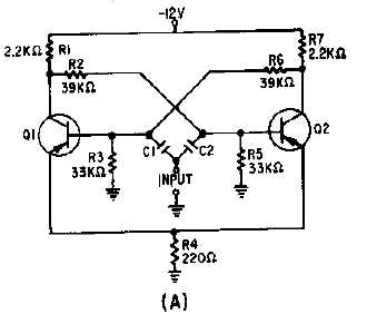
The bistable multivibrator circuit and the associated waveforms are shown in figure 3-17, views (A)
and (B), respectively. In this circuit, R1 and R7 are the collector load resistors. Voltage dividers R1, R2,
and R5 provide forward bias for Q2; R7, R6, and R3 provide forward bias for Q1. These resistors also
couple the collector signal from one transistor to the base of the other. Observe that this is direct coupling
of feedback. This type of coupling is required because the circuit depends on input triggers for operation,
not on RC time constants inside the circuit. Both transistors use common emitter resistor R4 which
provides emitter coupling. C1 and C2 couple the input triggers to the transistor bases.
Figure 3-17A.—Bistable multivibrator and waveforms.