3-14
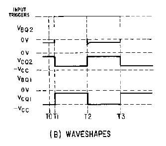
Figure 3-15B.—Monostable miltivibrator and waveshapes. Waveshapes
Note that R3 is variable to allow adjustment of the gate width. Increasing R3 increases the discharge
time for C1 which increases the cutoff time for Q2. Increasing the value of R3 widens the gate. To
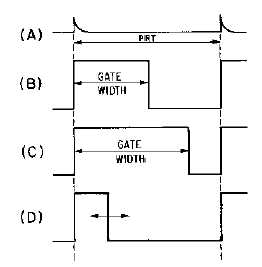
decrease the gate width, decrease the value of R3. Figure 3-16 shows the relationships between the trigger
and the output signal. View (A) of the figure shows the input trigger; views (B) and (C) show the
different gate widths made available by R3. Although the durations of the gates are different, the duration
of the complete cycle remains the same as the pulse repetition time of the triggers. View (D) of the figure
illustrates that the trailing edge of the positive alternation is variable.
Figure 3-16.—Monostable multivibrator waveforms with a variable gate.
The reason the monostable multivibrator is also called a one-shot multivibrator can easily be seen.
For every trigger pulse applied to the multivibrator, a complete cycle, or a positive and negative
alternation of the output, is completed.
Q5. In an astable multivibrator, which components determine the pulse repetition frequency?