3-17
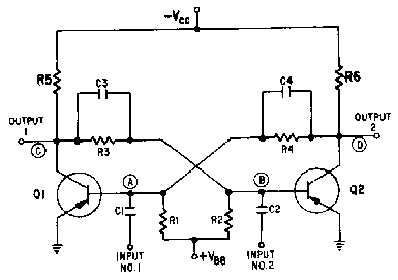
Figure 3-18.—Basic flip-flop.
Flip-flops are used in switching-circuit applications (computer logic operations) as counters, shift
registers, clock pulse generators, and in memory circuits. They are also used for relay-control functions
and for a variety of similar applications in radar and communications systems.
Notice that the basic flip-flop, illustrated in figure 3-18, has two inputs and two outputs. The inputs
are coupled to the bases of the transistors and the outputs are coupled from the collectors of the
transistors. Think of the flip-flop as two common-emitter amplifier circuits, where the output of one
amplifier is connected to the input of the other amplifier, and vice-versa. Point (D) is connected through
R4 to C4 to point (A). Point (A) is the input to transistor Q1. By the same token, point (C), which is the
output of Q1, is connected through R3 and C3 to the input (point (B)) of transistor Q2.
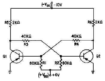
Taking a close look at the flip-flop circuit, you should be able to see how it maintains its stable
condition. Typical values for the resistors and applied voltages are shown in figure 3-19. The capacitors
have been removed for simplicity.
Figure 3-19.—Flip-flop (capacitors removed).