3-26
duration and frequency of such pulses are determined by the characteristics of a transformer and its
relationship to the circuit. Figure 3-33 shows a blocking oscillator. This is a simplified form used to
illustrate circuit operation.
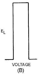
Figure 3-32B.—Voltage across a coil.
Figure 3-33.—Blocking oscillator.
When power is applied to the circuit, R1 provides forward bias and transistor Q1 conducts. Current
flow through Q1 and the primary of T1 induces a voltage in L2. The phasing dots on the transformer
indicate a 180-degree phase shift. As the bottom side of L1 is going negative, the bottom side of L2 is
going positive. The positive voltage of L2 is coupled to the base of the transistor through C1, and Q1
conducts more. This provides more collector current and more current through L1. This action is
regenerative feedback. Very rapidly, sufficient voltage is applied to saturate the base of Q1. Once the base
becomes saturated, it loses control over collector current. The circuit now can be compared to a small
resistor (Q1) in series with a relatively large inductor (L1), or a series RL circuit.