4-2
STANDING-WAVE RATIO (SWR) MEASUREMENTS
Standing-wave ratio (swr) is the ratio of the maximum voltage or current to the minimum voltage or
current at any point along a transmission line. Swr measurements are used to determine the matching
quality of the termination of the line.
A variety of methods and test equipments may be used to measure the voltage or current distribution
along a transmission line. An open transmission line is accessible for coupling to many types of voltage-
measuring devices, such as a wavemeter or a grid-dip meter. However, at higher frequencies where
coaxial cables or waveguides are used to minimize skin effect losses, (discussed in NEETS, module 10)
access is more complicated. Access to the interior of the waveguide or center conductor of the coaxial
cable must be gained by using a unidirectional or bidirectional coupler, which is inserted into the
transmission line. The coupler contains a slot into which an rf probe is inserted and positioned with
respect to directivity.
The conditions that produce standing waves and their adverse effects are discussed in detail in
NEETS, module 10. The different methods of detecting and measuring standing waves are discussed in
the following paragraphs.
PROBES
A magnetic or electric probe can be used to observe the standing wave on a short-circuited,
terminated line. The wavelength is obtained by measuring the distance between alternate maximum or
minimum current points along the line. A typical setup operating at 300 megahertz might use two 10-foot
lengths of number 14 phosphor-bronze wires, which are spaced 1 inch apart and supported parallel to a set
of probe guide rails. The line should be partially matched to the source generator by means of a parallel-
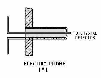
wire shorting stub connected in parallel with the transmission line and the oscillator output line. Figure 4-
1, view A and view B, illustrates the types of probes required for this method of measurement.
Figure 4-1A.—Typical electromagnetic probe.

