4-5
4. Adjust the rf voltage amplitude applied to the bridge until a full-scale meter reading is obtained.
5. Reconnect the bridge in the normal manner (resistor RL to the output terminals, etc.). If the meter
reading is now more than 1% or 2% of the full-scale reading, different arrangements (lead dress)
of the internal wiring must be tried until the null is reduced to 0 or as close as possible to the 0
point.
The bridge can be calibrated after completion of the preceding check. Connect the transmission line
under investigation to the output terminals of the bridge and connect a succession of noninductive
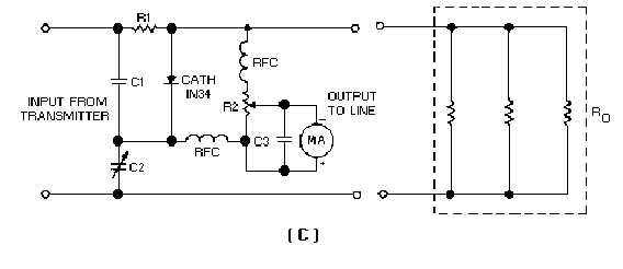
resistors (RO in view C) to the load end of the transmission line until the bridge is balanced. Assuming
that the bridge was originally balanced for the characteristic impedance of the line, the standing-wave
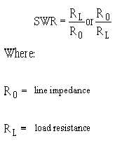
ratio can be computed from the following equation:
Figure 4-2C.—Resistance-capacitance bridge circuit for measuring standing-wave ratio.
Select the formula that yields a ratio greater than unity. The swr calibration can be recorded on the
meter scale directly, recorded on a chart in terms of the meter deflection, or plotted on a graph against the
meter deflection. The variable capacitor, in turn, can be calibrated for various characteristic impedances.
This is accomplished by applying suitable resistors (RO) across the output terminals and noting the
capacitor settings at the respective balance points. A range of 50 to 300 ohms should prove attainable.


