4-4
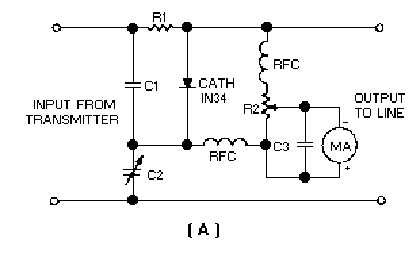
Figure 4-2A.—Resistance-capacitance bridge circuit for measuring standing-wave ratio.
However, the applied frequency must be low enough to avoid skin effect, stray inductance,
capacitance, and coupling between circuit elements and wiring. The leads must be kept short to eliminate
stray reactance, which causes bridge imbalance. The rectifier circuit wiring must be isolated from other
bridge component fields so that induced voltages do not cause an erroneous indication. You should only
use resistors having negligible capacitance and inductance effects.
Before you calibrate a newly constructed bridge, the following procedure must be followed if
residual readings caused by stray effects are to be held to a minimum:
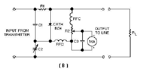
1. Connect a noninductive resistor (RL in view B) that is equal to the characteristic impedance of the
line to the output terminals of the bridge.
Figure 4-2B.—Resistance-capacitance bridge circuit for measuring standing-wave ratio.
2. Apply an rf voltage to the input terminals and adjust the variable capacitor for a minimum reading
on the meter.
3. Reconnect the resistor (R
L) to the input terminals and connect the rf power source to the output
terminals.


