4-7
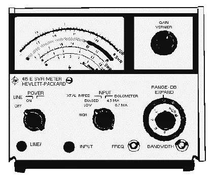
Figure 4-3.—Typical swr meter.
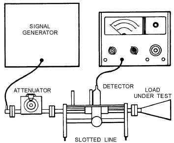
Figure 4-4 shows a typical swr measurement setup using the swr meter. The signal source is usually
a sinusoidal wave that is square-wave modulated at 1,000 hertz.
Figure 4-4.—Typical setup for measuring swr.
The swr meter usually gets its input from a detector, either a barretter or a crystal diode. This
detector must be a square-law device (its output voltage is proportional to the applied rf power) to ensure