4-8
the accuracy of the meter. The input is amplified and applied directly to the meter. To perform the
measurement as shown in figure 4-4, you move the detector along the slotted line so that its probe is at a
voltage maximum and adjust the gain of the meter with the RANGE-DB, GAIN, and VERNIER controls
(EXPAND switch to NORM) for full-scale deflection (1.0 on the 1.0 to 4 SWR scale). Then move the
probe toward a minimum. If the meter drops below 3.2, rotate the RANGE-DB switch one position
clockwise and read on the 3.2 to 10 SWR scale. If the pointer drops below this scale, rotate the RANGE-
DB switch one more position clockwise and read on the 1.0 to 4 scale and multiply by 10. This pattern
continues for still higher swr readings.
The dB scales can be used for a standing-wave-ratio measurement by setting the meter to full scale at
a voltage maximum, then turning the RANGE-DB switch clockwise for an on-scale reading at a voltage
minimum and noting the difference in dB reading at the maximum and minimum. A dB reading is
obtained by adding the RANGE-DB switch setting and meter indication. The swr meter may also be used
for high resolution insertion loss measurements.
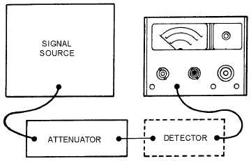
The setup for performing insertion loss or attenuation measurements is shown in figure 4-5. It
requires that you initially establish a convenient reference on the DB scale of the meter. This is
accomplished by connecting the signal source directly to the detector and using the GAIN and VERNIER
controls to adjust the meter pointer to a convenient reference. Then you can insert the device to be
measured between the signal source and the detector and note the change in dB, as shown on the meter.
Figure 4-5.—Typical setup for measuring attenuation or insertion loss.
ATTENUATION AND INSERTION LOSS MEASUREMENTS OF TRANSMISSION LINES
Transmission lines are sometimes subjected to extremes of weather and the corrosive effects of salt
water. You should be aware of the adverse effects of this environment on transmission lines and how to
determine electrical losses caused by transmission-line deterioration.
Q-3.
What are the two common causes of transmission-line deterioration?
LOSS MEASUREMENT
Insertion loss measurement of transmission lines requires the use of a good signal generator and an
accurate power meter. The method is identical to the insertion loss measurements used on most couplers.
When a known frequency, at a predetermined level of power, is inserted into one end of a transmission