4-28
DIRECTIVITY
The DIRECTIVITY of an antenna or an array can be determined by looking at its radiation pattern.
In an array propagating a given amount of energy, more radiation takes place in certain directions than in
others. The elements in the array can be altered in such a way that they change the pattern and distribute it
more uniformly in all directions. The elements can be considered as a group of antennas fed from a
common source and facing different directions. On the other hand, the elements could be arranged so that
the radiation would be focused in a single direction. With no increase in power from the transmitter, the
amount of radiation in a given direction would be greater. Since the input power has no increase, this
increased directivity is achieved at the expense of gain in other directions.
Directivity and Interference
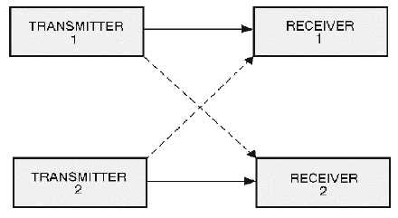
In many applications, sharp directivity is desirable although no need exists for added gain. Examine
the physical disposition of the units shown in figure 4-23. Transmitters 1 and 2 are sending information to
receivers 1 and 2, respectively, along the paths shown by the solid arrows. The distance between
transmitter 1 and receiver 1 or between transmitter 2 and receiver 2 is short and does not require high-
power transmission. The antennas of the transmitters propagate well in all directions. However, receiver 1
picks up some of the signals from transmitter 2, and receiver 2 picks up some of the signals from
transmitter 1, as shown by the broken arrows. This effect is emphasized if the receiving antennas intercept
energy equally well in all directions.
Figure 4-23.—Directivity and interference.
The use of highly directional arrays as radiators from the transmitters tends to solve the problem. The
signals are beamed along the paths of the solid arrows and provide very low radiation along the paths of
the broken arrows. Further improvement along these lines is obtained by the use of narrowly directed
arrays as receiving antennas. The effect of this arrangement is to select the desired signal while
discriminating against all other signals. This same approach can be used to overcome other types of
radiated interference. In such cases, preventing radiation in certain directions is more important than
producing greater gain in other directions.
Look at the differences between the field patterns of the single-element antenna and the array, as
illustrated in figure 4-24. View A shows the relative field-strength pattern for a horizontally polarized
single antenna. View B shows the horizontal-radiation pattern for an array. The antenna in view A