4-26
often referred to as a COMBINATION ARRAY or an ARRAY OF ARRAYS. Since maximum radiation
occurs at right angles to the plane of the array, the term broadside array is also used.
The FRONT-TO-BACK RATIO is the ratio of the energy radiated in the principal direction
compared to the energy radiated in the opposite direction for a given antenna.
PHASING
Various reflected and refracted components of the propagated wave create effects of reinforcement
and cancellation. At certain distant points from the transmitter, some of the wave components meet in
space. Reception at these points is either impaired or improved. If the different components arrive at a
given point in the same phase, they add, making a stronger signal available. If they arrive out of phase,
they cancel, reducing the signal strength.
Radiation Pattern
Effects similar to those described in the preceding paragraph can be produced at the transmitting
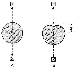
point itself. Consider the antennas shown in figure 4-21, views A and B. View A shows an unobstructed
view of the radiation pattern of a single dipole. In view B two dipoles, shown as points 1 and 2, are
perpendicular to the plane of the page. They are spaced 1/4 wavelength apart at the operating frequency.
The radiation pattern from either antenna 1 or 2, operating alone, would be uniform in all directions in
this plane, as shown in view A. Suppose that current is being fed to both antennas from the same
transmitter in such a way that the current fed to antenna 2 lags the current in antenna 1 by 90 degrees.
Energy radiating from antenna 1 toward receiving location X will reach antenna 2 after 1/4 cycle of
operation. The energy from both antennas will add, and propagation toward X will be strong.
Figure 4-21.—Phasing of antenna in free space.
Radiation from antenna 2 toward receiving location Y will reach antenna 1 after 1/4 cycle. The
energy in antenna 1 was 1/4 cycle behind that of antenna 2 to begin with; therefore, the radiation from
antenna 1 toward receiving point Y will be exactly 180 degrees out of phase with that of antenna 2. As a
result, the radiation fields will cancel and there will be no radiation toward Y.
At receiving points away from the line of radiation, phase differences occur between 0 and 180
degrees, producing varying amounts of energy in that direction. The overall effect is shown by the