2-24
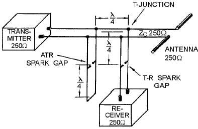
Figure 2-14.—Parallel-connected duplexer showing distance and impedance.
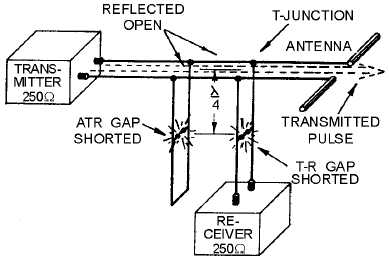
Figure 2-15.—Parallel-connected duplexer during transmission.
During the transmitting pulse, an arc appears across both spark gaps and causes the tr and atr circuits
to act as shorted (closed-end) quarter-wave stubs. The circuits then reflect an open circuit to the tr and atr
circuit connections to the main transmission line. None of the transmitted energy can pass through these
reflected opens into the atr stub or into the receiver. Therefore, all of the transmitted energy is directed to
the antenna.
During reception, as shown in figure 2-16, the amplitude of the received echo is not sufficient to
cause an arc across either spark gap. Under this condition, the atr circuit now acts as a half-wave
transmission line terminated in a short-circuit. This is reflected as an open circuit at the receiver
T-junction, three-quarter wavelengths away. The received echo sees an open circuit in the direction of the
transmitter. However, the receiver input impedance is matched to the transmission line impedance so that
the entire received signal will go to the receiver with a minimum amount of loss.


