2-25
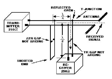
Figure 2-16.—Parallel-connected duplexer during reception.
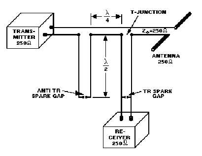
Series-Connected Duplexer Operation
In the SERIES-CONNECTED DUPLEXER SYSTEM, shown in figure 2-17, the tr spark gap is
located one-half wavelength from the receiver T-junction. The atr spark gap is located one-half
wavelength from the transmission line and three-quarters wavelength from the receiver T-junction.
During transmission, the tr and atr gaps fire in the series-connected duplexer system, as shown in figure
2-18. This causes a short-circuit to be reflected at the series connection to the main transmission line one-
half wavelength away. The transmitted pulse "sees" a low impedance path in the direction of the antenna
and does not go into the atr stub or the receiver.
Figure 2-17.—Series-connected duplexer showing distance and impedance.