2-28
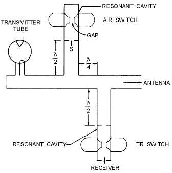
Figure 2-21.—Branched waveguide duplexer.
Maximum use of the received signals is ensured by an atr tube. The transmitted pulse travels from
the magnetron to the atr branch where part of the energy is diverted into the gap. A slot (S) is placed
across the waveguide one-half wavelength from the main guide, and passes the rf energy through it and
into the cavity. The cavity builds up the electric field that breaks down the gap, detunes the cavity, and, as
a result, effectively closes the slot. One-half wavelength away, this action effectively closes the entrance
to the atr branch and limits the amount of energy entering the atr branch to a small value.
Most of the energy is, therefore, directed down the guide to the antenna. Upon reaching the receiver
branch, the same effect is produced by the tr tube in the receiver line. Because the energy entering both
openings is effectively limited by the gaps, maximum energy is transferred between the magnetron and
the antenna.
During the resting time, the atr spark gap is not broken down by the received signals. The received
signal sets up standing waves within the cavity that cause it to resonate. At resonance, the low impedance
of the atr cavity is reflected as a high impedance at the entrance to the transmitter waveguide (three-
quarter wavelength away). This ensures that the maximum received signal will enter the receiver branch.
Hybrid Ring Duplexer
The HYBRID RING is used as a duplexer in high-power radar systems. It is very effective in
isolating the receiver during transmission. A simplified version of the hybrid-ring duplexer is shown in
views A and B of figure 2-22. The operation of the duplexer, in terms of the E field distribution during
transmission and reception, is illustrated in views C and D. The H lines, though present, have been
omitted to simplify the explanation.


