2-32
RECEIVER BLOCK DIAGRAM
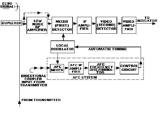
The SUPERHETERODYNE receiver is almost always used in microwave radar systems. A typical
superheterodyne radar receiver is shown in figure 2-23. A receiver of this type meets all the requirements
listed above. Signals from the antenna enter the receiver via the duplexer. A low-noise rf amplifier is
usually the first stage of modern radar receivers. Some receivers, however, send the antenna signal
directly to the mixer, as shown by the dashed path. The low-noise amplifiers used in modern systems are
usually solid-state devices, such as tunnel-diode, parametric, or microwave transistor amplifiers.
Figure 2-23.—Typical superheterodyne radar receiver.
The MIXER stage is often called the FIRST DETECTOR. The function of this stage is to convert the
received rf energy to a lower, intermediate frequency (IF) that is easier to amplify and manipulate
electronically. The intermediate frequency is usually 30 or 60 megahertz. It is obtained by heterodyning
the received signal with a local-oscillator signal in the mixer stage. The mixer stage converts the received
signal to the lower IF signal without distorting the data on the received signal.
After conversion to the intermediate frequency, the signal is amplified in several IF AMPLIFIER
stages. Most of the gain of the receiver is developed in the IF amplifier stages. The overall bandwidth of
the receiver is often determined by the bandwidth of the IF stages.
The output of the IF amplifiers is applied to the SECOND DETECTOR. It is then rectified and
passed through one or more stages of amplification in the video amplifier(s). The output stage of the
receiver is normally an emitter follower. The low-impedance output of the emitter follower matches the
impedance of the cable. The video pulses are coupled through the cable to the indicator for video display
on the crt.


