2-37
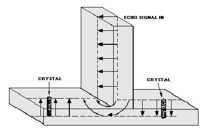
Figure 2-26B.—Balanced mixer fields. WAVEGUIDE AND ECHO SIGNAL ARM.
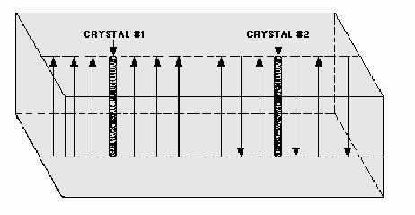
Figure 2-26C.—Balanced mixer fields. WAVEGUIDE.
A difference in phase exists between echo signals applied across the two crystals. The signal applied
to the crystals from the local oscillator is in phase. Therefore, at some point both signals applied to crystal
#1 will be in phase, and the signals applied to crystal #2 will be out of phase. This means that an IF signal
of one polarity will be produced across crystal #1 and an IF signal of the opposite polarity will be
produced across crystal #2. When these two signals are applied to the balanced output transformer (figure
2-25), they will add. Outputs of the same polarity will cancel across the balanced transformer.
This action eliminates the noise of the local oscillator. Noise components introduced from the local
oscillator are in phase across the crystals and are, therefore, cancelled in the balanced transformer. The rf
characteristics of the crystals must be nearly equal, or the noise of the local oscillator will not completely
cancel. Note that only the noise produced by the local oscillator is canceled. Noise arriving with the echo
signal is not affected.


