2-38
IF Amplifier Stage
The IF AMPLIFIER SECTION of a radar receiver determines the gain, signal-to-noise ratio, and
effective bandwidth of the receiver. The typical IF amplifier (commonly called an IF strip) usually
contains from three to ten amplifier stages. The IF amplifier has the capability to vary both the bandpass
and the gain of a receiver. Normally, the bandpass is as narrow as possible without affecting the actual
signal energy. When a selection of pulse widths is available, such as short and long pulses, the bandpass
must be able to match the bandwidth of the two different signals. Gain must be variable to provide a
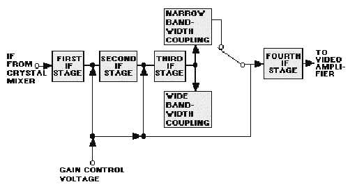
constant voltage output for input signals of different amplitudes. Figure 2-27 is a block diagram of an IF
amplifier that meets these requirements.
Figure 2-27.—IF amplifier block diagram.
The most critical stage of the IF section is the input (first stage). The quality of this stage determines
the noise figure of the receiver and the performance of the entire receiving system with respect to
detection of small objects at long ranges. Gain and bandwidth are not the only considerations in the
design of the first IF stage. A consideration perhaps of more importance is noise generation. Noise
generation in this stage must be low. Noise generated in the input IF stage will be amplified by
succeeding stages and may exceed the echo signal in strength.
Detectors
The detector in a microwave receiver serves to convert the IF pulses into video pulses. After
amplification, these are applied to the indicator. The simplest form of detector, and the one most
commonly used in microwave receivers, is the DIODE DETECTOR.
A diode detector circuit is shown in view A of figure 2-28. The secondary of T1 and C1 form a tuned
circuit that is resonant at the intermediate frequency. Should an echo pulse of sufficient amplitude be
received, the voltage (ei) developed across the tuned circuit is an IF pulse. Its shape is indicated by the
dashed line in view B. Positive excursions of e
i
cause no current to flow through the diode. However,
negative excursions result in a flow of diode current and a subsequent negative voltage (eo) to be
developed across R1 and C2. Between peak negative voltage excursions of the ei wave, capacitor C2
discharges through R1. Thus, the eo waveform is a negative video pulse with sloping edges and


