5-8
The output from the selected demodulator is amplified by the audio amplifier and presented
simultaneously to the HEADSET jack, AUDIO OUT terminals, and the speaker.
You should note that this receiver, as with most others, requires no other special equipment. It uses a
standard df loop or a whip antenna. If it is installed in a submarine, a trailed, (towed) long-wire antenna
may be used.
MICROWAVE
Communications systems in the 1 gigahertz to 10 gigahertz portion of the radio frequency spectrum
use line-of-sight propagation. Propagation takes place in the lower atmosphere (troposphere). It is
affected by factors such as barometric pressure, temperature, water vapor, turbulence, and stratification
(forming of atmospheric layers).
A typical microwave transmitter includes an exciter group, a modulator group, a power amplifier,
and power supplies. The transmitter usually has a power output of about 1 watt. When a higher output is
required (about 5 watts), a traveling-wave tube (twt) is used as the amplifier. (A twt is a high-gain, low-
noise, wide-bandwidth microwave amplifier. It is capable of gains of 40 decibels or more, with
bandwidths of over an octave. The twt was discussed in chapter 2 of NEETS, Module 11, Microwave
Principles.) A typical microwave receiver contains an rf-IF group, local oscillator, demodulator, and
amplifier. Both transmitters and receivers contain special circuits because of the high operating
frequencies and critical frequency stability requirements.
Line-of-Sight System
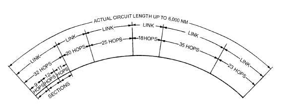
A line-of-sight (los) microwave system consists of one or more point-to-point hops as shown in
figure 5-7. Each hop is designed so that it can be integrated into a worldwide communications network.
Los systems have many characteristics. In these systems, propagation is only affected by changes in the
troposphere. The distance between microwave system hop points ranges from 50 to 150 kilometers (31 to
95 statute miles). These systems are capable of handling up to 600 4-kilohertz voice channels and can also
transmit television. These signals can usually be transmitted with less than 10 watts of power. Both the
transmit and receive antennas are horn-driven paraboloids that provide high gain and narrow beam
widths. In some applications, as shown in figure 5-8, plane reflectors are used with the paraboloids. These
systems are very reliable. They are designed to operate over 99 percent of the time. These systems are
well adapted to multichannel communications and closed circuit television.
Figure 5-7.—Typical hop-link and section allocation.


