5-4
and has the impedance characteristics of the antenna.) The dummy load is impedance matched to the pa.
It allows testing of the pa without putting a signal on the air. When the equipment is in an operating
mode, the dummy load is not used. The helix house is a small building physically separated from the
transmitter location. It contains antenna loading, coupling, and tuning circuits. The main components
consist of a HELIX (large coil) and variable inductors. The signal is fed from the helix directly to the
antenna. Sometimes two antennas are used.
Antenna designs vary with the amount and type of land available, desired signal coverage, and
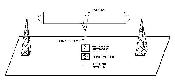
bandwidth requirements. Figure 5-2 shows a simplified transmit antenna. The Navy uses TOP-HAT (flat-
top) capacitive loading with one or more radiating elements. Typical top hat antennas consist of two or
more lengths of wire parallel to each other and to the ground, each fed at or near its mid point. The
lengths of wire are usually supported by vertical towers. These antennas may take many shapes. The
matching network shown is in the helix house. Figure 5-3 shows the installation at the naval
communications unit in Cutler, Maine. The Navy has several of these types of installations. They are used
primarily for fleet broadcasts and have power outputs in the .25- to 2-megahertz range. You should notice
the transmitter, the location of the helix houses, and the dual antennas. You should also notice the
transmission line tunnel. It is underground and over a half-mile long. Figure 5-4, view (A) and view (B),
shows another antenna configuration. This array of monopoles (quarter-wave, vertically polarized stubs)
is referred to as a TRIATIC antenna. A triatic antenna is a special form of a rhombic-arranged monopole
array. This type of array is designed to transmit from a particular location. Triatics are all basically the
same but have some design differences at each site. The physical differences compensate for differences
in terrain. Now that we have looked at the transmit side, let's look at the receive side.
Figure 5-2.—Simplified vlf transmitting antenna.