5-9
Figure 5-8.—Parabolic antenna and passive reflector combination.
Now let us take a look at another system. It is called the tropospheric-scatter microwave system. But
first, you may want to review tropospheric propagation in NEETS, Module 10, Introduction to Wave
Propagation, Transmission Lines, and Antennas.
Tropospheric Scatter System
A tropospheric-scatter (tropo-scatter) microwave system gets results similar to those of the line-of-
sight system. It does it in a different way. The los system uses towers to relay information.
The tropo system uses the turbulence in the layer between the troposphere and the stratosphere to
bounce signals back to earth. This method provides several hops and communications beyond los. The
propagation reliability and communications capability is the same. The transmission range is up to 800
kilometers (500 statute miles). Transmitter output power may be up to 75 kilowatts depending on the
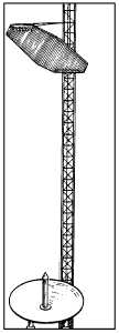
operational requirements. The antennas are horn-driven paraboloids and may be as large as 50 to 60 feet
in diameter. Figure 5-9 shows a typical tropospheric-scanner antenna. Remember that hf has a hop
distance (skywave) of about 1,400 miles; the distance of one hop for a line-of-sight system is between 31
and 95 miles. The tropospheric-scatter system conveniently fills the gap between these distances.