2-39
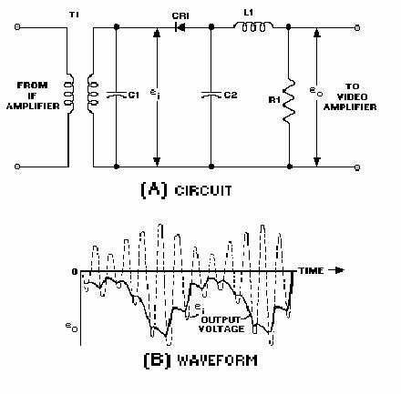
superimposed IF ripple, as indicated by the solid line in view B. A negative polarity of the output pulse is
ordinarily preferred, but a positive pulse may be obtained by reversing the connections of the diode. In
view A, inductance L1, in combination with wiring capacitance and C2, forms a low-pass filter. This filter
attenuates the IF components in the eo waveform but results in a minimum loss of video high-frequency
components.
Figure 2-28.—Diode detector.
Video Amplifiers
The video amplifier receives pulses from the detector and amplifies these pulses for application to
the indicating device. A video amplifier is fundamentally an RC coupled amplifier that uses high-gain
transistors or pentodes. However, a video amplifier must be capable of a relatively wide frequency
response. Stray and interelectrode capacitances reduce the high-frequency response of an amplifier, and
the reactance of the coupling capacitor diminishes the low-frequency response. These problems are
overcome by the use of FREQUENCY COMPENSATION NETWORKS in the video amplifier. The
types of frequency compensation networks that may be used in a video amplifier stage are discussed in
detail in NEETS, Module 8, Introduction to Amplifiers.
Q38. What receiver circuit actually produces the IF frequency?
Q39. The IF amplifiers are connected in what amplifier configuration?
Q40. Which receiver component converts the IF pulses to video pulses?


