2-44
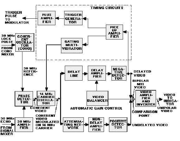
Figure 2-31.—Mti block diagram.
The phase detector produces a video signal. The amplitude of the video signal is determined by the
phase difference between the coho reference signal and the IF echo signals. This phase difference is the
same as that between the actual transmitted pulse and its echo. The resultant video signal may be either
positive or negative. This video output, called coherent video, is applied to the 14-megahertz cw carrier
oscillator.
The 14-megahertz cw carrier frequency is amplitude modulated by the phase-detected coherent
video. The modulated signal is amplified and applied to two channels. One channel delays the
14-megahertz signal for a period equal to the time between transmitted pulses. The signal is then amplified
and detected. The delay required (the period between transmitted pulses) is obtained by using a mercury
delay line or a fused-quartz delay line, which operates ultrasonically at 14 megahertz.
The signal to the other channel is amplified and detected with no delay introduced. This channel
includes an attenuating network that introduces the same amount of attenuation as does the delay line in
the delayed video channel. The resulting nondelayed video signal is combined in opposite polarity with
the delayed signal. The amplitude difference, if any, at the comparison point between the two video
signals is amplified; because the signal is bipolar, it is made unipolar. The resultant video signal, which
represents only moving targets, is sent to the indicator system for display.
An analysis of the mti system operation just described shows that signals from fixed targets produce
in the phase detector recurring video signals of the same amplitude and polarity. (Fixed targets have an
unchanging phase relationship to their respective transmitted pulses.) Thus, when one video pulse is


