2-28
Q-37.
What is the purpose of R2?
Q-38.
If C4 were removed from the circuit, what would happen to the output of the amplifier?
Q-39.
What components form the load for Q1?
Q-40.
How many tuned parallel LC circuits are shown in this schematic?
Q-41.
What do the dotted lines connecting C1, C2, C5, and C6 indicate?
Q-42.
What is the purpose of C3?
SUMMARY
This chapter has presented information on video and rf amplifiers. The information that follows
summarizes the important points of this chapter.
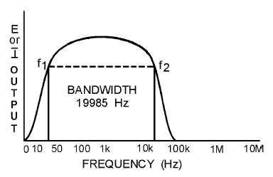
A FREQUENCY-RESPONSE CURVE will enable you to determine the BANDWIDTH and the
UPPER and LOWER FREQUENCY LIMITS of an amplifier.
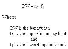
The BANDWIDTH of an amplifier is determined by the formula:


