2-21
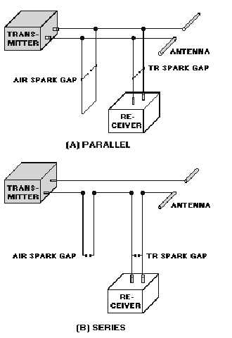
(spark gaps) connected in a microwave circuit with three terminal transmission lines, one each for the
transmitter, receiver, and antenna. As shown in views A and B of figure 2-12, these circuits may be
connected in parallel or in series. Both systems will be discussed in detail in this section. One tube is
called the TRANSMIT-RECEIVER TUBE, or TR TUBE; the other is called the ANTITRANSMIT-
RECEIVE TUBE, or ATR TUBE. The tr tube has the primary function of disconnecting the receiver, and
the atr tube of disconnecting the transmitter.
Figure 2-12.—Duplexer systems.
The overall action of the tr and atr circuits depends upon the impedance characteristics of the
quarter-wavelength section of transmission line. A quarter-wavelength, or an odd multiple of the quarter-
wavelength, transmission line presents opposite impedance values at the ends; one end of the line appears
as a short and the other end appears as an open.
TR Tube
The type of spark gap used as a tr tube may vary. It may be one that is simply formed by two
electrodes placed across the transmission line; or it may be one enclosed in an evacuated glass envelope
with special features to improve operation. The requirements of the spark gap are (1) high impedance
prior to the arc and (2) very low impedance during arc time. At the end of the transmitted pulse the arc


