2-17
Frequency drift is compensated for, in part, by the use of automatic frequency control (afc) circuits
designed to control the frequency of the local oscillator in the receiver system. This, however, does not
completely eliminate the undesirable effects of frequency drift on mti operation.
The power-amplifier transmitter system does the same thing as the keyed-oscillator transmitter but
with fewer stability problems. It generates, shapes, and amplifies pulses of rf energy for transmission.
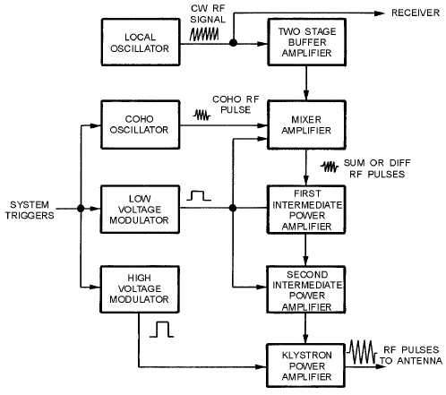
Figure 2-10 is a block diagram of a typical power-amplifier transmitter system. In this transmitter
system a multicavity klystron tube amplifies lower-powered rf pulses that have been generated and
shaped in other stages. CROSSED-FIELD AMPLIFIERS (AMPLITRONS) are used in radar systems
with a wide band of transmitted frequencies because they are stable over a wider frequency range. A
crossed-field amplifier transmitter is discussed later in this section.
Figure 2-10.—Power amplifier transmitter block diagram.
In figure 2-10, the power-amplifier chain input signals are generated by heterodyning (mixing) two
frequencies. That is, two different frequencies are fed to a mixer stage (mixer amplifier) and the resultant,
either the sum or difference frequency, may be selected as the output. (The operation of mixer circuits is
explained in more detail in the section on receivers.) The low-power pulse is then amplified by
intermediate power amplifier stages and applied to the klystron power-amplifier. The klystron power-
amplifier concentrates the rf output energy into a very narrow frequency spectrum. This concentration
makes the system more sensitive to smaller targets. In addition the detection range of all targets is
increased.


