2-26
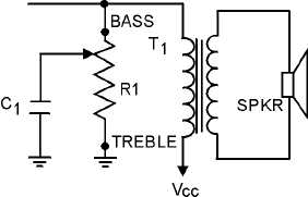
Figure 2-23.—Variable tone control using an RC filter.
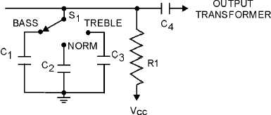
A switch-type, variable tone control is illustrated in figure 2-24. With this method we use a three-
position switch to provide fixed degrees of tone control. When tone control S1 is in the BASS position,
capacitor C1 bypasses the high frequencies and provides bass emphasis. With S1 in the normal (NORM)
position, C2 acts as the bypass, and a moderate amount of high-frequency attenuation is accomplished.
This position provides balanced bass and treble response. When S1 is in the TREBLE position, C3 acts as
the bypass and provides minimum high-frequency attenuation and maximum treble emphasis. As a rule of
thumb, you can figure the capacitance of C2 is approximately five times the value of C3, and C1 is
approximately ten times the value of C3. For example with C3 at .001 microfarads, C2 would be .005
microfarads, and C1 would be .01 microfarads.
Figure 2-24.—Switch tone control.
Crystal Filters
A quartz crystal, used as a selective filter in the IF section of a communications receiver, is one of
the most effective methods of achieving maximum selectivity. It is especially useful when the channel is
crowded and considerable noise (both external and internal) is present.
One possible circuit arrangement is shown in figure 2-25. Let’s look at the theory involved in
understanding this circuit. You can see a crystal in one leg of the bridge circuit. The secondary of the
input transformer (T1) is balanced to ground through the center tap connection. The crystal acts as a high
Q series resonant circuit. It allows signals within the immediate vicinity of resonance to pass through the
crystal to the output coil (L3). The desired signal appears between the center tap of L3 and ground.


