2-21
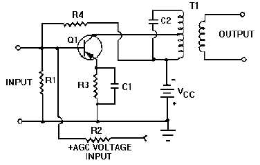
controlled degenerative feedback. Use of an npn transistor, in the same configuration, would require the
agc voltage to possess a negative potential.
Figure 2-17.—Common emitter amplifier with agc.
FORWARD AND REVERSE AGC.—When we use an agc voltage to cause degeneration by
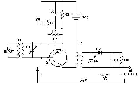
driving the amplifiers toward cutoff, it is referred to as REVERSE agc. Figure 2-18 shows the type of agc
circuitry normally used with this method. A second method that uses agc is an application called
FORWARD agc. In the case of forward agc, you'll find the amplifier is driven toward the saturation
region of its characteristic curve. (Sometimes referred to as an energy diagram.)
Figure 2-18.—Reverse agc.
Let’s look at our example. Assume the agc voltage is negative. Under this condition, Q1 is self
biased; under no-signal conditions, it is operating well up on its characteristic curve. When a signal is
applied, negative agc voltage is developed in the detector circuit and fed back to Q1, which increases


