2-29
more than the other and produce a control signal. This system remains unbalanced at all times because
any change in frequency is instantaneously corrected. The network between the diodes and oscillator is
essentially a low-pass filter. This filter prevents discriminator pulses from reaching the oscillator.
FREQUENCY SYNTHESIS
In present day communications systems, long term accuracy of one part in a million is required from
many of the frequency generators (local oscillators) used in communications equipment. Variable
frequency oscillators cannot practically achieve this high degree of stability. Therefore, a system known
as FREQUENCY SYNTHESIS has been developed to meet the stringent demands for stability. This
system uses circuitry that produces a signal frequency through a heterodyning and frequency selection
process. This signal is not harmonically related to any of the signals used in the heterodyning process. It
is also not related to the selected crystal frequency. This makes the signal unique.
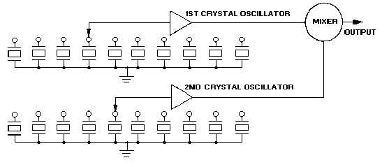
Figure 2-28 is a multiple crystal, frequency synthesizer that produces desired output frequencies by
mixing frequencies from several crystal oscillators. Each oscillator uses ten or more crystals to control its
operating frequency. This provides for a large number of output frequency combinations. Figure 2-29 is a
practical frequency synthesizer in which the harmonics and subharmonics of a single standard oscillator
are combined to provide a wide multichoice of output signals. Each of these signals is harmonically
related to a subharmonic of the standard oscillator. You will find the primary difficulty encountered in the
frequency synthesizers is the presence of spurious signals generated in the "combining mixers." Extensive
filtering and extremely careful selection of operating frequencies are required for even the simplest
circuits. Spurious frequency problems increase and channel spacing decreases as the range of operating
frequencies increases.
Figure 2-28.—Multiple crystal frequency synthesizer.

