6-19
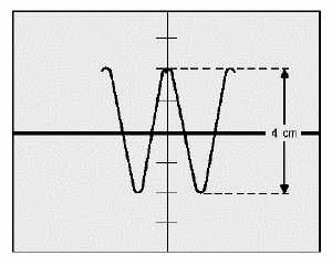
Figure 6-22.—Sine wave attenuation.
The vertical attenuator control (VOLTS/DIV in figure 6-19) provides a means of adjusting the input
signal level to the amplifiers by steps. These steps are sequenced from low to high deflection factors. The
potentiometer control (VAR in figure 6-19) provides a means of fine, or variable, control between steps.
This control may be mounted separately, or it may be mounted on the attenuator control. When the
control is mounted separately, it is often marked as FINE GAIN or simply GAIN. When mounted on the
attenuator control, it is usually marked VARIABLE or VAR.
The variable control adds attenuation to the step that is selected. Since accurately calibrating a
potentiometer is difficult, the variable control is either left unmarked or the front panel is marked off in
some convenient units, such as 1-10 and 1-100. The attenuator control, however, can be accurately
calibrated. To do this, you turn off the variable control to remove it from the attenuator circuit. This
position is usually marked CAL (calibrate) on the panel, or an associated light indicates if the VAR
control is on or off. In figure 6-19, the light called UNCAL indicates the VAR control is in the
uncalibrated position.
COMPONENTS USED TO SELECT THE VERTICAL OPERATING MODE
As we discussed earlier, channel 1 is being used to discuss basic operating procedures for the
oscilloscope. Figure 6-23 shows how the vertical mode of operation is selected. The VERT MODE
section contains push-button switches that enable you to select channel 1, channel 2, and several other
vertical modes of operation. For the present discussion, note only that CH 1 is selected by these switches.


