6-18
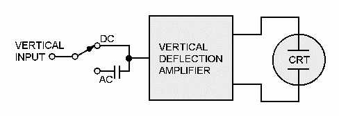
Figure 6-20.—Vertical input arrangement.
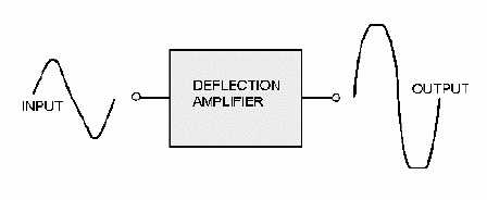
The VERTICAL-DEFLECTION AMPLIFIER increases the amplitude of the input signal level
required for the deflection of the CRT beam. The deflection amplifier must not have any other effect on
the signal, such as changing the shape (called DISTORTION). Figure 6-21 shows the results of distortion
occurring in a deflection amplifier.
Figure 6-21.—Deflection amplifier distortion.
Attenuator Control
An amplifier can handle only a limited range of input amplitudes before it begins to distort the
signal. Signal distortion is prevented in oscilloscopes by the incorporation of circuitry that permits
adjustment of the input signal amplitude to a level that prevents distortion from occurring. This
adjustment is called the ATTENUATOR control in some scopes (VOLTS/DIV and VAR in figure 6-19).
This control extends the usefulness of the oscilloscope by enabling it to handle a wide range of signal
amplitudes.
The attenuator usually consists of two controls. One is a multiposition (VOLTS/DIV) control, and
the other is a variable (VAR) potentiometer. Each position of the control may be marked either as to the
amount of voltage required to deflect the beam a unit distance, such as VOLTS/DIV, or as to the amount
of attenuation (called the DEFLECTION FACTOR) given to the signal, such as 100, 10, or 1.
Suppose the .5 VOLTS/DIV position were selected. In this position, the beam would deflect
vertically 1 division for every 0.5 volts of applied signal. If a sine wave occupied 4 divisions peak-to-
peak, its amplitude would be 2 volts peak-to-peak (4 0.5), as shown in figure 6-22.


