6-16
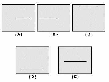
Figure 6-18.—Effects of horizontal and vertical controls.
In view A, the horizontal control has been adjusted to move the trace too far to the right; in view B,
the trace has been moved too far to the left. In view C, the vertical POSITION control (discussed later)
has been adjusted to move the trace too close to the top; in view D, the trace has been moved too close to
the bottom. View E (figure 6-18) shows the trace properly positioned.
10X MAG (Magnifier) Switch
The 10X MAG (magnifier) switch (figure 6-16) allows you to magnify the displayed signal by a
factor of 10 in the horizontal direction. This ability is important when you need to expand the signal to
evaluate it carefully.
COMPONENTS USED TO DETERMINE THE AMPLITUDE OF A SIGNAL
We will now discuss the dual-trace components of the scope. You will use these components to
determine the amplitude of a signal. Notice in figure 6-19 that the highlighted section at the upper left of
the scope looks just the same as the section at the lower left of the scope. This reveals the dual-trace
capability section of the scope. The upper left section is the CH (channel) 1 input and is the same as the
CH 2 input at the lower left. An input to both inputs at the same time will produce two independent traces
on the CRT and use the dual-trace capability of the scope.


