2-6
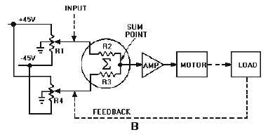
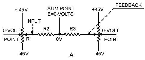
View B shows a more in-depth illustration of view A. With the wiper arms of R1 and R4 at the
midpoint of travel, the voltage from the wiper arm to ground is zero volts. Therefore, zero volts would
also be measured at the connection point between R2 and R3 (the summation point). This means that the
error signal is zero. With no input signal, the amplifier output is zero; therefore, the motor shaft remains
stationary.
Figure 2-3B.—Block diagram of a position servo.
For the purpose of explanation, imagine that the R1 wiper arm is mechanically moved upward to a
new position where a voltage between the wiper arm and ground measures +10 volts. Further
measurement shows zero volts between the wiper arm of R4and ground. Since R
2
and R3 are of equal
values, +5 volts is measured between the sum point and ground because 5 volts is dropped across each
resistor. The +5 volts at the sum point is the "error" signal.
As shown in figure 2-4, (view A, view B, and view C),when no error is present, the voltage at the
sum point is zero. This is because the network composed of R1, R2, R
3, and R4 is balanced. When the
wiper of R
1
is moved toward +45 volts, the network becomes unbalanced as shown in view B. The left-
hand side of R
2
becomes positive. This causes current to flow from +45 volts through R3 and R2 to the
+10 volts at the left side of R2. Because R2 and R3 are of equal value, the voltage drops then will be equal;
therefore, the voltage at the sum point will equal +5 volts.
Figure 2-4A.—Development of the error signal.


