1-23
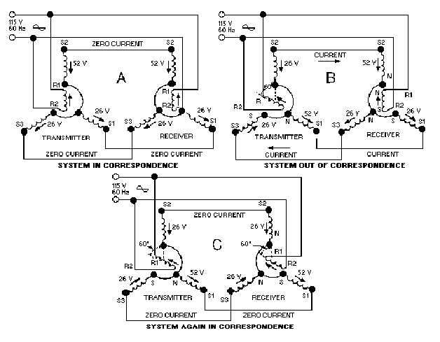
Figure 1-16.—A simple synchro transmission system.
When both transmitter and receiver rotors in a synchro system are on zero or displaced from zero by
the same angle, a condition known as CORRESPONDENCE exists. In view A of figure 1-16, the
transmitter and receiver are shown in correspondence. In this condition, the rotor of the TR induces
voltages in its stator coils (S2 = 52V; S1 and S3 = 26V) that are equal to and opposite the voltages
induced into the TX stator coils (S2 = 52V; S1 and S3 = 26V). This causes the voltages to cancel and
reduces the stator currents to zero. With zero current through the coils, the receiver torque is zero and the
system remains in correspondence.
The angle through which a transmitter rotor is mechanically rotated is called a SIGNAL. In view B
of figure 1-16, the signal is 60º. Now, consider what happens to the two synchros in correspondence when
this signal is generated
When the transmitter rotor is turned, the rotor field follows and the magnetic coupling between the
rotor and stator windings changes. This results in the transmitter S2 coil voltage decreasing to 26 volts,
the S3 coil voltage reversing direction, and the S1 coil voltage increasing to 52 volts. This imbalance in
voltages, between the transmitter and receiver, causes current to flow in the stator coils in the direction of
the stronger voltages. The current flow in the receiver produces a resultant magnetic field in the receiver
stator in the same direction as the rotor field in the transmitter. A force (torque) is now exerted on the
receiver rotor by the interaction between its resultant stator field and the magnetic field around its rotor.
This force causes the rotor to turn through the same angle as the rotor of the transmitter. As the receiver


