1-25
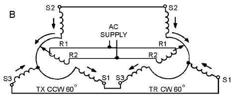
Figure 1-17B.—Effect of reversing the S1 and S3 connections between the transmitter and the receiver.
Even when the S1 and S3 connections are reversed, the system at 0º acts the same as the basic
synchro system we previously described at 0º. This is because the voltages induced in the S1 and S3
stator windings are still equal and oppose each other. This causes a canceling effect, which results in zero
stator current and no torque. Without the torque required to move the receiver rotor, the system remains in
correspondence and the reversing of the stator connections has no noticeable effect on the system at 0º.
Suppose the transmitter rotor is turned counterclockwise 60º, as shown in view A of figure 1-17. The
TX rotor is now aligned with S1. This results in maximum magnetic coupling between the TX rotor and
the S1 winding. This maximum coupling induces maximum voltage in S1. Because S1 is connected to S3
of the TR, a voltage imbalance occurs between them. As a result of this voltage imbalance, maximum
current flows through the S3 winding of the TR causing it to have the strongest magnetic field. Because
the other two fields around S2 and S1 decrease proportionately, the S3 field has the greatest effect on the
resultant TR stator field. The strong S3 stator field forces the rotor to turn 60º clockwise into alignment
with itself, as shown in view B. At this point, the rotor of the TR induces canceling voltages in its own
stator coils and causes the rotor to stop. The system is now in correspondence. Notice that by reversing S1
and S3, both synchro rotors turn the same amount, but in OPPOSITE DIRECTIONS.
We must emphasize that the only stator leads ever interchanged, for the purpose of reversing receiver
rotation, are S1 and S3. S2 cannot be reversed with any other lead since it represents the electrical zero
position of the synchro. As you know, the stator leads in a synchro are 120º apart. Therefore, any change
in the S2 lead causes a 120º error in the synchro system and also reverses the direction of rotation.
In new or modified synchro systems, a common problem is the accidental reversal of the R1 and R2
leads on either the transmitter or receiver. This causes a 180º error between the two synchros, but the
direction of rotation remains the same.
Q-28. What two receiver leads are reversed to reverse the rotor's direction of rotation?
Q-29. What is the most likely problem if the transmitter shaft reads 0º when the receiver shaft indicates
180º?
TORQUE DIFFERENTIAL SYNCHRO SYSTEMS
The demands on a synchro system are not always as simple as positioning an indicating device in
response to information received from a single source (transmitter). For example, an error detector used in
checking weapons equipment uses a synchro system to determine the error in a gun's position with respect
to the positioning order. To do this, the synchro system must accept two signals, one containing the
positioning order and the other corresponding to the actual position of the gun. The system must then


