1-26
compare the two signals and position an indicating dial to show the difference between them, which is the
error.
Obviously, the simple synchro transmitter-receiver system discussed so far could not handle a job of
this sort. A different type of synchro is needed, one which can accept two signals simultaneously, add or
subtract the signals, and furnish an output proportional to their sum or difference. This is where the
SYNCHRO DIFFERENTIAL enters the picture. A differential can perform all of these functions.
There are two types of differential units - differential transmitters and differential receivers. The
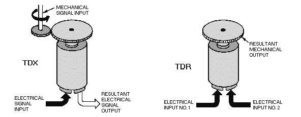
differential transmitter (TDX) accepts one electrical input and one mechanical input and produces one
electrical output. The differential receiver (TDR) accepts two electrical inputs and produces one
mechanical output. A comparison of the TDX and TDR is shown in figure 1-18. The torque differential
transmitter and the torque differential receiver can be used to form a DIFFERENTIAL SYNCHRO
SYSTEM. The system can consist either of a torque transmitter (TX), a torque differential transmitter
(TDX), and a torque receiver (TR), (TX-TDX-TR); or two torque transmitters (TXs) and one torque
differential receiver (TDR), (TX-TDR-TX). Before beginning a discussion of the systems using
differentials, we need to provide a brief explanation on the newly introduced synchros, the TDX and the
TDR.
Figure 1-18.—Torque differentials.
Torque Differential Transmitter
In the torque differential transmitter, BOTH the rotor and stator windings consist of three Y-
connected coils, as illustrated in view A of figure 1-19. The stator is normally the primary, and receives
its input signal from a synchro transmitter. The voltages appearing across the differential's rotor terminals
(R1, R2, and R3) are determined by the magnetic field produced by the stator currents, the physical
positioning of the rotor, and the step-up turns ratio between the stator and the rotor. The magnetic field,
created by the stator currents, assumes an angle corresponding to that of the magnetic field in the
transmitter supplying the signal. The position of the rotor controls the amount of magnetic coupling that
takes place between the stator magnetic field and the rotor, and therefore, the amount of voltage induced
into the rotor windings. If the rotor position changes in response to a mechanical input, then the voltages
induced into its windings also change. Therefore, the output voltage of the TDX varies as a result of either
a change in the input stator voltage or a change in the mechanical input to the rotor. This electrical output
of the TDX may be either the SUM or the DIFFERENCE of the two inputs depending upon how the three
units (the TX, the TDX, and the TR) are connected.


