1-31
Now, consider what happens in view D when the TX rotor is turned manually to 75º and the TDX
rotor is set manually on 30º. When the TX rotor is turned to 75º, magnetic coupling increases between the
rotor and S1. This, in turn, increases the voltage in S1 and, therefore, the magnetic field surrounding it. At
the same time, the field in S2 and S3 decreases proportionately. This causes the resultant TX stator field
to line up in the direction of its rotor. The increased voltage in S1 of the TX also causes an increase in
current flow through S1 in the TDX, while decreased currents flow through S2 and S3. Therefore, a
strong magnetic field is established around the S1 winding in the TDX. This field has the greatest effect
on the resultant TDX stator field and causes it to line up in the same relative direction as the TX stator
field (75º). The TDX stator field does not move from this 75º position because it is controlled by the
position of the TX rotor. However, its angular position with respect to the R2 winding decreases by 30
when the TDX rotor is turned. Therefore, the signal induced into the TDX rotor and transmitted to the TR
is 45º. The TR rotor responds to the transmitted signal and turns counterclockwise to 45º. This system has
just solved the equation 75º
-
30º = 45º.
TX-TDX-TR System Operation (Addition)
Frequently it is necessary to set up a TX-TDX-TR system for addition. This is done by reversing the
S1 and S3 leads between the TX and the TDX, and the R1 and R3 leads between the TDX and the TR.
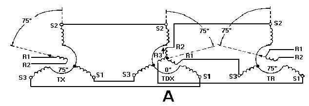
With these connections, the system behaves as illustrated in figure 1-21. Consider what happens when the
TX rotor is turned to 75º, while the TDX is set at 0º view A. In the TX, with the rotor at 75º, increased
coupling between the rotor and S1 increases the current in, and consequently the magnetic field around,
that coil. At the same time, the field strengths of S2 and S3 decrease proportionately. This causes the
resultant field of the TX stator to rotate counterclockwise and align itself with its rotor field. The system
is now connected so the increased current in S1 of the TX flows through S3 of the TDX, while decreased
currents flow through S1 and S2. Therefore, in the TDX, the resultant stator field is shifted 75º clockwise
because of the stronger field around S3. Since the rotor of the TDX is on 0º, the voltage in the rotor is not
changed but simply passed on to the TR. Remember, the R1 and R3 leads between the TDX and the TR
have also been reversed. Just as in the simple TX-TR system with S1 and S3 leads interchanged, torque is
developed in the TR, which turns the rotor in a direction opposite to the rotation of the TDX stator field.
Therefore, the TR rotor rotates 75º counterclockwise and aligns itself with the TX rotor. Thus, the TX-
TDX-TR system connected for addition behaves in the same way as the system connected for subtraction
as long as the TDX rotor remains on 0º. When this condition exists, the TR rotor follows the TX rotor
exactly. As you can see, the system in view. A just solved the equation 75º + 0º = 75º.
Figure 1-21A.—TX-TR system operation (addition).