1-20
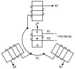
Figure 1-13.—Synchro transmitter.
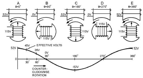
Figure 1-14 illustrates a cross section of a synchro transmitter and shows the effective voltage
induced in one stator coil as the rotor is turned to different positions. The turns ratios in synchros may
vary widely, depending upon design and application, but there is commonly a 2.2:1 stepdown between the
rotor and a single coil. Thus, when 115 volts is applied to the rotor, the highest value of effective voltage
induced in any one stator coil is 52 volts. The maximum induced voltage occurs each time there is
maximum magnetic coupling between the rotor and the stator coil (views A, C, and E). The effective
voltage induced in the secondary winding is approximately equal to the product of the effective voltage
on the primary, the secondary-to-primary turns ratio, and the magnetic coupling between primary and
secondary. Therefore, because the primary voltage and the turns ratio are constant, it is commonly said
that the secondary voltage varies with the angle between the rotor and the stator.
Figure 1-14.—Stator voltage vs rotor position.
When stator voltages are measured, reference is always made to terminal-to-terminal voltages
(voltage induced between two stator terminals) instead of to a single coil's voltage. This is because the


