1-15
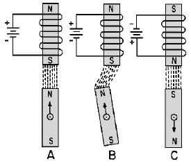
Figure 1-8.—Operation of an electromagnet with a bar-magnet rotor.
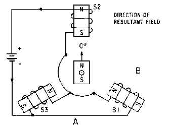
Keeping in mind these basic points, consider how the bar magnet reacts to three electromagnets
spaced 120º apart as illustrated in figure 1-9. In this figure, stator coils S1 and S3, connected in parallel,
together have the same field strength as stator coil S2. The magnetic field is determined by current flow
through the coils. The strongest magnetic field is set up by stator coil S2, since it has twice the current and
field strength as either S1 or S3 alone. A resultant magnetic field is developed by the combined effects of
the three stator fields. Coil S2 has the strongest field, and thus, the greatest effect on the resultant field,
causing the field to align in the direction shown by the vector in view B of the figure. The iron-bar rotor
aligns itself within the resultant field at the point of greatest flux density. By convention, this position is
known as the zero-degree position. The rotor can be turned from this position to any number of positions
by applying the proper combination of voltages to the three coils, as illustrated in figure 1-10, view (A),
view (B), view (C), view (D), view (E), view (F).
Figure 1-9.—Operation of three electromagnets spaced 120º apart.


