1-11
This type of winding is frequently used in both transmitters and receivers.
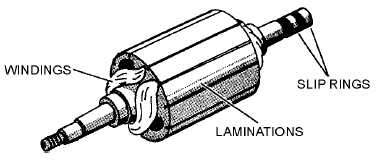
The drum or wound rotor has coils wound in slots in a laminated core as shown in figure 1-6. This
type of rotor is used in most synchro control transformers and differential units, and occasionally in
torque transmitters. It may be wound continuously with a single length of wire or may have a group of
coils connected in series. The single continuous winding provides a distributed winding effect for use in
transmitters. When the rotor is wound with a group of coils connected in series, a concentrated winding
effect is provided for use in control transformers. When used in differential units, the rotor is wound with
three coils so their magnetic axes are 120º apart.
Figure 1-6.—Drum or wound rotor.
Both types of synchro rotors have their coils wound on laminated cores that are rigidly mounted on a
shaft. To enable the excitation voltage to be applied to the rotor winding, two slip rings are mounted on
one end of the shaft and insulated from the shaft to prevent shorting. An insulated terminal board,
mounted on the end of the cylindrical frame, houses the brushes, which ride on the slip rings. These
brushes provide continuous electrical contact to the rotor during its rotation. Also mounted on the rotor
shaft are low-friction ball bearings, which permit the rotor to turn easily.
STATOR CONSTRUCTION
The stator of a synchro is a cylindrical structure of slotted laminations on which three Y-connected
coils are wound with their axes 120º apart. In figure 1-7, view A shows a typical stator assembly
consisting of the laminated stator, stator windings, and cylindrical frame; view B shows the stator
lamination and the slots in which the windings are placed. Some synchros are constructed so both the
stator and the rotor may be turned. Electrical connections to this type of stator are made through slip rings
and brushes.


