1-9
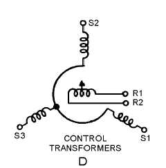
Figure 1-3D.—Schematic symbols for synchros.
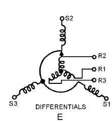
Figure 1-3E.—Schematic symbols for synchros.
Q8. On the synchro schematic symbol, what indicates the angular displacement of the rotor?
SYNCHRO CONSTRUCTION
Figure 1-4 shows a cutaway view of a typical synchro. Having the knowledge of how a synchro is
constructed should enable you to better understand how synchros operate.


