1-18
Notice in figure 1-10, in views A C, and E, that the rotor positions are achieved by shifting the total
current through different stator windings (S1, S2, and S3). This causes the rotor to move toward the coil
with the strongest magnetic field. To obtain the rotor positions in views B, D, and F, it was necessary only
to reverse the battery connections. This causes the direction of current flow to reverse and in turn reverses
the direction of the magnetic field. Since the rotor follows the magnetic field the rotor also changes
direction. By looking closely at these last three rotor positions, you will notice that they are exactly
opposite the first three positions we discussed. This is caused by the change in the direction of current
flow. You can now see that by varying the voltages to the three stator coils, we can change the current in
these coils and cause the rotor to assume any position we desire.
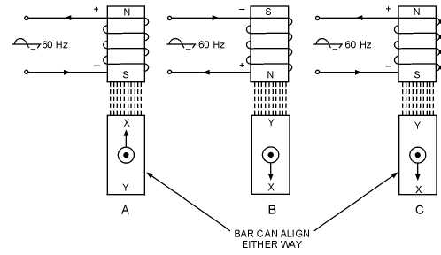
In the previous examples, dc voltages were applied to the coils. Since synchros operate on ac rather
than dc, consider what happens when ac is applied to the electromagnet in figure 1-11. During one
complete cycle of the alternating current, the polarity reverses twice.
Figure 1-11.—Operation of an electromagnet with ac voltage.
Therefore, the number of times the polarity reverses each second is twice the excitation frequency, or
120 times a second when a 60-Hz frequency is applied. Since the magnetic field of the electromagnet
follows this alternating current, the bar magnet is attracted in one direction during one-half cycle (view A)
and in the other direction during the next half cycle (view B). Because of its inertia, the bar magnet
cannot turn rapidly enough to follow the changing magnetic field and may line up with either end toward
the coil (view C). This condition also causes weak rotor torque. For these reasons, the iron-bar rotor is not
practical for ac applications. Therefore, it must be replaced by an electromagnetic rotor as illustrated in
figure 1-12.


