2-25
DEMODULATORS IN THE SERVO SYSTEM
As you know, servo systems use both ac and dc servo motors depending upon the requirements of
the system. Systems that are required to move light loads at constant speed use ac motors. Systems that
are required to move heavy loads with a wide speed range use dc motors. When the requirements of the
system call for a dc motor or other dc devices, the ac error signal within the servo system must be
converted to a dc error signal before being fed to the dc servo amplifier. The conversion is made by the
circuit known as a DEMODULATOR.
As with the modulator, the demodulator maintains the same relationships between its input and
output signals. Just like the modulator, the demodulator's output amplitude is proportional to its input
signal and its output polarity is determined by the phase of the input signal. These relationships, as in the
modulator you just studied, are necessary so the "new" error signal will control the servo motor in the
desired manner.
Diode Demodulator
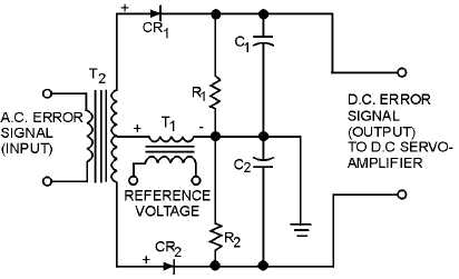
One example of a servo demodulator is the DIODE DEMODULATOR, sometimes called a phase
detector, shown in figure 2-18. This circuit is used in servo systems because it not only converts ac to dc,
but it is also able to distinguish the phase of the ac signal by comparing it to a reference voltage. Do not
confuse this circuit with other phase detector circuits, such as those used in radar or communications
systems. This demodulator (phase detector) distinguishes signals that are either in phase or 180º out of
phase. For this reason this circuit is useful in servo systems where the ac output from the error detector
(CT) is either in phase with the reference signal or 180º out of phase. Whatever type of error detector is
used in the servo system, the reference voltage to the error detector and to the demodulator must be IN
PHASE with each other for the demodulator to do its job.
Figure 2-18.—Diode demodulator.
As shown in figure 2-18, the anodes of the two diodes are supplied with the same reference voltage.
With no ac error input signal applied to T2 (quiescent state), both diodes will conduct equally on the
positive half-cycle of the reference voltage. The voltage drops across R11 and R2 are equal. This results in
the two output terminals being at the same potential; therefore, the output voltage is zero for the positive
half-cycle. During the negative half-cycle, a negative voltage is felt on the anodes of both diodes, both


