2-20
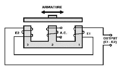
Figure 2-14.—Basic-E transformer.
When the armature is located in the center of the E-shaped core, as shown in the figure, equal and
opposite voltages are induced in the secondary coils. The difference between them is zero. Thus, the
voltage at the output terminals is also zero.
But, if the armature is moved, say to the tight, the voltage induced in coil 1 increases, while the
voltage induced in coil 3 decreases. The two voltages are then unequal, so that the difference is no longer
zero. A net voltage results at the output terminals. The amplitude of this voltage is directly proportional to
the distance the armature has been moved from its center position. The phase of this output voltage,
relative to the ac on the primary, controls the direction the load moves in correcting the error.
The basic E-transformer will detect movement of the armature in one axis only (either the horizontal
or vertical depending upon the way the unit is mounted). To detect movement in both the horizontal and
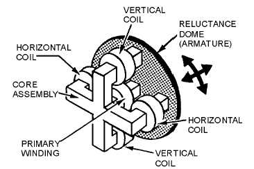
vertical axes, a CROSSED-E-TRANSFORMER is used.
If you place two E-transformers at right angles to each other and replace the bar armature with a
dome-shaped one (fig. 2-15), you have the basic configuration of what is known as the crossed-E
transformer, or pickoff. In most applications the dome-shaped armature is attached to a gyro, and the core
assembly is fixed to a gimbal, which is the servo load.
Figure 2-15.—Crossed-E transformer.


