2-22
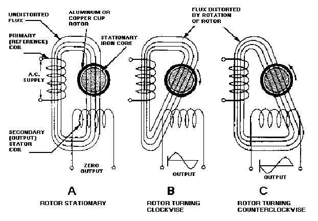
winding. Flux lines cut the secondary winding, and a voltage is induced in the output winding as shown in
views B and C. The amount of magnetic field that will be distorted is determined by the speed of the
rotor. Therefore, the magnitude of the voltage induced in the secondary winding is proportional to the
rotor's velocity (speed).
Figure 2-16.—Ac drag-cup rate generator.
The direction of the magnetic field's distortion is determined by the direction of the rotor's motion. If
the rotor is turned in one direction, the lines of flux will cut the secondary winding in one direction. If the
motion of the rotor is reversed, the lines of flux will cut the secondary winding in the opposite direction.
Therefore, the phase of the voltage induced in the secondary winding, measured with respect to the phase
of the supply voltage, is determined by the direction of the rotor's motion. The phase relationship is
shown in views B and C at the output winding.
The frequency of the tachometer generator output voltage is the same as the frequency of the
reference voltage. The output voltage is generated by the primary alternating flux field cutting the
secondary winding; therefore, the output voltage must have the same frequency as the supply voltage.
Other types of ac tachometer generators have a squirrel-cage rotor. Otherwise their construction and
principles of operation are identical to the drag-cup type.


