2-28
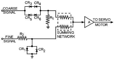
Figure 2-19.—Semiconductor diode synchronizing network.
When the load is within 3º of correspondence, the coarse signal is no longer large enough to forward
bias the coarse diode network. The effect of this is to cause a large impedance across the diode network,
which then drops most of the coarse signal. Practically no coarse signal voltage is felt across R1 and one
leg of the summing network. On the other hand, the fine signal is also small at this time, since the load is
close to correspondence. Small fine signals are unaffected by CR
1
and CR2. Therefore, the small fine
signal is impressed across the summing network. With the fine signal being the only signal felt at the
summing network, it takes control and drives the load to the exact point of correspondence. There are
various types of synchronizing circuits used in servo systems. Some applications call for electron tubes,
relays, and different types of semiconductor diodes. The theory of the specific type you will encounter in
servo equipments will be explained in detail in the equipment's technical manual.
Q-24. What is the purpose of a synchronizing network in a servo system?
MAGNETIC AMPLIFIERS
As we stated earlier in this chapter, various types of servo amplifiers are used to drive servo motors.
When the amplifier is required to produce a large amount of power, the conventional electronic amplifier
becomes less efficient than some other types. The following is a brief discussion of a typical magnetic
amplifier used in a servo system where large amounts of power are required to move a heavy load. If you
need to refresh your memory on the theory of the magnetic amplifier, refer to Module 8 of this training
series, Introduction to Amplifiers.
Magnetic Amplifiers in a Servo
Figure 2-20 illustrates a magnetic amplifier being used as the output stage of a servo amplifier.