5-28
techniques are applicable over the entire electronic spectrum from vlf to ehf and are generally limited
only by your resourcefulness and the basic limitation of the equipment employed. The basic swept-
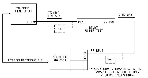
frequency arrangement is shown in figure 5-28.
Figure 5-28.—Frequency-response test.
The swept-frequency technique can effectively determine the frequency response of an amplifier or
filter and is useful in the alignment or bandwidth determination of an IF or rf stage. The test equipment
permits direct visual readout on the crt of the spectrum analyzer. The spectrum analyzer can also be
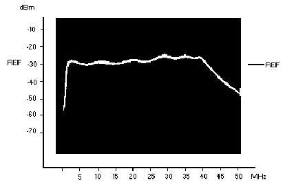
connected to an X-Y chart recorder if a permanent record or print is desired. Figure 5-29 shows a
spectrum analyzer crt display of the frequency response of a multicoupler. The tracking generator used
must be capable of sweeping the desired frequency range of the device under test.
Figure 5-29.—Typical spectrum analyzer frequency-response display.


