5-24
Q-7.
When referring to spectrum analyzers, what is meant by the term resolving signals?
TIME-DOMAIN REFLECTOMETRY
TIME-DOMAIN REFLECTOMETRY is a testing and measurement technique that has found
increasing usefulness in testing transmission lines (both metallic and fiber-optic), cables, strip lines,
connectors, and other wideband systems or components. Basically, time-domain reflectometry is an
extension of an earlier technique in which reflections from an electrical pulse were monitored to locate
faults and to determine the characteristics of power transmission lines. You can compare time-domain
reflectometry to a closed-loop radar system in which the transmitted signal, a very fast step pulse, is fed
into the system and the reflections resulting from discontinuities or impedance deviations in the system
are monitored on a crt.
The technique used in time-domain reflectometry consists of feeding an impulse of energy into the
system and then observing that energy as it is reflected by the system at the point of insertion. When the
fast-rise input pulse meets with a discontinuity or impedance mismatch, the resultant reflections appearing
at the feed point are compared in phase, time, and amplitude with the original pulse. By analyzing the
magnitude, deviation, and shape of the reflected waveform, you can determine the nature of the
impedance variation in the transmission system. Also, since distance is related to time and the amplitude
of the reflected step is directly related to impedance, the comparison indicates the distance to the fault as
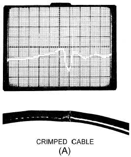
well as the nature of the fault. Figure 5-25, view A, view B, view C, and view D, illustrates typical
transmission line problems that can easily be identified by using a time-domain reflectometer (tdr). In
addition to showing both the distance to and the nature (resistive, inductive, or capacitive) of each line
discontinuity, time-domain reflectometry also reveals the characteristic impedance of the line and
indicates whether losses are shunt or series. They are also used to locate and analyze connectors and
splices.
Figure 5-25A.—Time-domain reflectometer display of transmission line problems.


