6-36
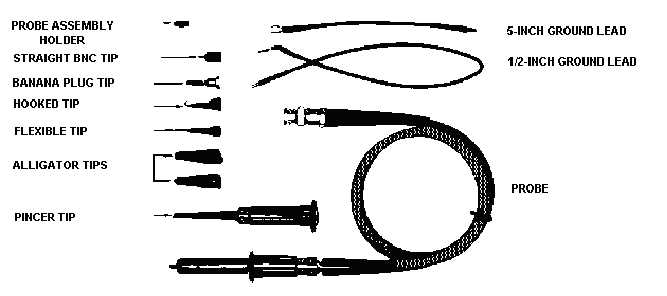
Figure 6-40.—Common probe tips.
In choosing the probe to use for a particular measurement, you must consider such factors as circuit
loading, signal amplitude, and scope sensitivity.
The 1-to-1 probe offers little or no attenuation of the signal under test and is, therefore, useful for
measuring low-level signals. However, circuit loading with the 1-to-1 probe may be a problem. The
impedance at the probe tip is the same as the input impedance of the oscilloscope.
An attenuator probe has an internal high-value resistor in series with the probe tip. This gives the
probe a higher input impedance than that of the oscilloscope. Because of the higher input impedance, the
probe can measure high-amplitude signals that would overdrive the vertical amplifier if connected
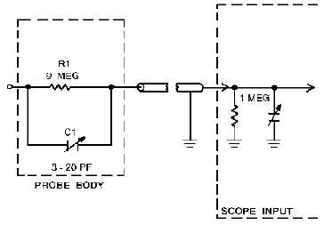
directly to the oscilloscope. Figure 6-41 shows a schematic representation of a basic attenuation probe.
The 9-megohm resistor in the probe and the 1-megohm input resistor of the oscilloscope form a 10-to-1
voltage divider.
Figure 6-41.—Basic attenuation probe.


