6-32
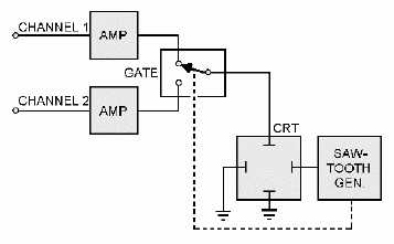
Figure 6-35.—ALT (alternate) mode.
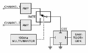
Figure 6-36.—CHOP mode.
The output dc voltage references on each of the amplifiers are independently adjustable. Therefore,
the beam will be deflected by different amounts on each channel if the voltage reference is different at
each amplifier output. The output voltage from each amplifier is applied to the deflection plates through
the gate. The gate is actually an electronic switch. In this application, it is commonly referred to as a
BEAM SWITCH.
Switching is controlled by a high-frequency multivibrator in the CHOP mode. That is, the gate
selects the output of one channel and then the other at a high-frequency rate (1200 kilohertz in most
oscilloscopes). Because the switching time is very short in a good-quality oscilloscope, the resultant
display is two sets of horizontally dashed lines, as shown in figure 6-37, view A.


