6-38
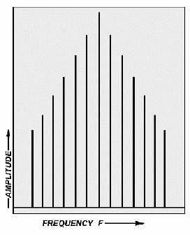
Figure 6-42.—Spectrum analyzer pattern.
BASIC FUNCTIONAL DESCRIPTION
The model 492 analyzer can be divided into six basic sections, as follows:
Converter section;
Intermediate frequency (IF) section;
Display section;
Frequency control section;
Digital control section; and
Power and cooling section.
Converter Section
The converter section actually consists of three frequency converters, made up of a mixer, local
oscillator (LO), and required filters. Only one frequency can be converted at a time and pass through the
filters to reach the next converter. The analysis frequency can, however, be changed by altering the
frequency of the LO and adjusting the FREQUENCY control knob.
FIRST CONVERTER.—The first (front end) converter changes the input signal to a usable IF
signal that will either be 829 MHz or 2072 MHz. The IF signal to be produced is dependent on which
measurement band selection is currently being used. The 829 MHz IF signal will be selected for bands 2
through 4, while the 2072 MHz IF signal is selected for bands 1 and 5 through 11.
Q-18. The first converter is also known by what other name?


